- Why Two Shot Molding Matters for Your Designs
- How Two Shot Molding Actually Works
- The Make-or-Break Decision
- Design for Manufacturing: Getting Your Part Right
- Real-World Engineering Applications
- Process Control and Troubleshooting
- Design Validation Checklist
- Seamless Transition from Your Current Process
- Frequently Asked Questions

Why Two Shot Molding Matters for Your Designs
Two shot molding (also called 2K injection molding, dual-shot molding, or bi-injection molding) eliminates the assembly gap that plagues traditional multi-material products. Instead of bonding pre-molded components with adhesives or mechanical fasteners—both prone to failure—this process creates molecular-level material integration within a single manufacturing cycle.
The engineering advantage is clear: You achieve permanent material bonds, eliminate tolerance stack-up from assembly operations, and reduce total part count in your Bill of Materials. For production volumes exceeding 50,000 units annually, the economics typically favor two shot molding over conventional assembly methods.
The global two shot injection molding market reached $10.6 billion in 2024, with 8.5% projected annual growth driven by automotive electrification, medical device complexity, and consumer electronics miniaturization demands.
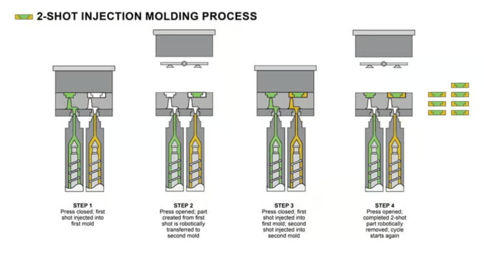
How Two Shot Molding Actually Works
The Rotary Platen System
Understanding the mechanical sequence is critical for design optimization:
Cycle Breakdown:
-
First Shot Injection (Substrate Formation)
- Rigid thermoplastic (PC, ABS, PA) injects into cavity A
- Mold temperature: 60-90°C to maintain surface energy
- Cooling to 70-85% crystallinity (not fully solidified)
- Cycle time: 15-45 seconds depending on wall thickness
-
Precision Rotation
- Rotary platen indexes 180 degrees
- Positioning accuracy: ±0.01mm critical for material interface
- Substrate moves to cavity B position
- Simultaneous first shot begins for next component
-
Second Shot Injection (Overmold Application)
- Elastomer (TPE/TPU) injects onto warm substrate
- Melt temperature 10-30°C below substrate’s melt point
- Injection pressure: 800-1400 bar for proper cavity filling
- Pack time: 2-5 seconds for molecular diffusion
-
Final Cooling & Ejection
- Both materials cool simultaneously
- Total cycle: 30-90 seconds for typical parts
- Automatic ejection without manual handling
Key Engineering Advantage: The substrate remains at 40-60°C above its glass transition temperature during second shot injection, enabling superior molecular bonding compared to traditional overmolding where the substrate fully cools between operations.
Why This Beats Traditional Overmolding
Traditional overmolding requires:
- Part removal after first shot
- Transfer to second machine or fixture (introduces positioning error)
- Fully cooled substrate (weaker chemical bonding)
- Manual or robotic handling (adds cycle time and cost)
Two shot molding eliminates all these variables. Your dimensional accuracy improves from ±0.15mm (typical overmolding) to ±0.02mm, and bond strength increases 40-60% due to optimized thermal conditions.
The Make-or-Break Decision
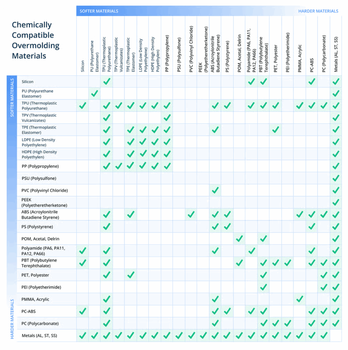
Understanding Material Compatibility
The substrate-overmold interface determines product durability. You need both chemical affinity and thermal compatibility:
Material Pairing Strategy Matrix:
| Substrate Material | Compatible Overmolds | Bond Mechanism | Peel Strength | Design Notes |
|---|---|---|---|---|
| Polycarbonate (PC) | TPE-U (TPU), TPE-S | Strong chemical + van der Waals | 12-18 N/mm | Best overall bonding; minimal mechanical features required |
| ABS | TPE-S, TPE-U (TPU) | Moderate chemical + physical | 10-14 N/mm | Excellent for consumer products; cost-effective |
| Polyamide (PA6/PA66) | TPE-A, TPU, Copolyamides | Chemical + moisture-assisted | 8-12 N/mm | Requires mechanical interlocks; hygroscopic considerations |
| Polypropylene (PP) | TPE-O (Olefinic), TPE-S | Primarily mechanical | 6-10 N/mm | Must have undercuts/grooves; limited chemical bonding |
| PC/ABS Blend | TPU, TPE-S | Balanced chemical | 11-15 N/mm | Good compromise for cost vs. performance |
Critical Thermal Windows
Your processing window must accommodate both materials:
First Shot (Substrate) Parameters:
- PC: Melt 280-320°C, Mold 60-90°C
- ABS: Melt 220-260°C, Mold 50-80°C
- PA66: Melt 260-290°C, Mold 70-110°C
- PP: Melt 200-240°C, Mold 30-60°C
Second Shot (Elastomer) Parameters:
- TPU: Melt 180-220°C, must be <substrate melt by 30°C minimum
- TPE-S: Melt 160-200°C, lower mold temps 40-60°C
- TPE-O: Melt 170-210°C, matches PP thermal profile
Why the temperature differential matters: If your TPE melt temperature approaches the substrate’s melt point, you risk substrate deformation. Maintain at least a 30°C safety margin.
Achieving Maximum Bond Strength
You need both chemical and mechanical bonding working together:
Chemical Bonding Optimization
Molecular diffusion occurs when polymer chains interpenetrate at the interface. To maximize:
- Substrate Surface Temperature: Keep at 40-60°C above Tg during second injection
- Mold Temperature Control: Higher mold temps (within material limits) increase chain mobility
- Pack Pressure and Time: 2-5 seconds at 60-80% injection pressure promotes interdiffusion
- Material Grade Selection: Choose materials with similar solubility parameters when possible
Practical tip: If peel testing shows clean substrate/overmold separation (no material tearing), your chemical bonding is insufficient. Increase mold temperature by 10-15°C increments and extend pack time.
Mechanical Interlocking Design
Even with excellent chemical bonding, add mechanical features for redundancy:
Undercut Design Guidelines:
| Feature Type | Recommended Dimensions | Pull Force Increase | Design Complexity |
|---|---|---|---|
| Simple Undercuts | 0.5-1.0mm depth, 60° angle | +100% | Low (side actions) |
| Grooves | 1.5-2.5mm wide × 1.0mm deep | +150% | Medium (must clear substrate) |
| Through-Holes | Ø2.0-5.0mm | +200-300% | Low (perfect for cylindrical parts) |
| Texture | SPI C-2 or coarser | +30-50% | Very Low (mold finishing) |
Critical rule for PP substrates: Since polypropylene has minimal chemical affinity with most TPEs, mechanical interlocking is mandatory. Design grooves every 8-12mm on grip surfaces.
Design for Manufacturing: Getting Your Part Right
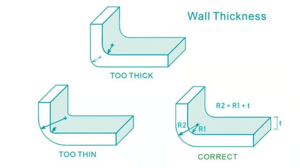
Wall Thickness Strategy
Non-uniform walls create differential cooling rates, leading to warpage and sink marks. This is amplified in two shot molding because you’re managing two materials with different shrinkage:
Fundamental Guidelines:
- Maintain Uniformity: Target ±20% thickness variation maximum
- Transition Gradually: No more than 25% thickness change per 3mm flow length
- Material-Specific Ranges:
| Material | Minimum Wall | Optimal Range | Maximum Wall | Shrinkage Rate |
|---|---|---|---|---|
| PC | 1.0mm | 1.5-2.5mm | 3.8mm | 0.5-0.7% |
| ABS | 1.2mm | 2.0-3.0mm | 3.5mm | 0.4-0.6% |
| PA66 | 0.76mm | 1.5-2.3mm | 2.9mm | 0.8-1.2% |
| PP | 0.64mm | 1.5-2.5mm | 3.8mm | 1.0-2.5% |
| TPE | 1.5mm | 2.0-4.0mm | 6.0mm | 1.5-3.0% |
Engineering insight: TPE overmolds can compensate for minor substrate warpage (up to 0.3mm) through their compliance, but don’t rely on this—fix the substrate design first.
Shut-Off Zone Design: Preventing Flash and Ensuring Clean Transitions
The shut-off zone is where the second mold half seals against your first-shot substrate. Poor design here causes 80% of two shot molding quality issues.
Critical Design Elements:
-
Accent Groove (Step Feature)
- Purpose: Creates sharp material boundary and prevents flash
- Dimensions: 1.5-2.0mm depth × 0.8-1.0mm width
- Location: Exactly at material transition line
- Result: Acts as a "flash trap" if any occurs
-
Shut-Off Surface Draft
- Minimum: 3 degrees (absolute minimum)
- Recommended: 5 degrees for textured surfaces
- Why: Reduces mold wear; ensures tight seal under clamping force
- Calculate: For every 10mm depth, provide 0.5-0.9mm per side taper
-
Compression Depth
- Typical: 0.05-0.15mm into substrate
- Purpose: Ensures seal without deforming first shot
- Monitor: Check for witness marks on production parts
Common failure mode: Flash occurs when shut-off pressure is insufficient or substrate has shrunk more than anticipated. Solution: Increase accent groove depth to 2.5mm and verify substrate cooling time allows adequate solidification.
Gate and Runner Optimization
Poor gate placement creates weld lines in high-stress areas and weak material interfaces.
Strategic Gate Positioning:
First Shot Gates:
- Locate in non-critical cosmetic areas (will be covered by second shot when possible)
- Avoid areas where second shot must bond (high stress from gate area)
- Use hot-tip gates to minimize visible marks
- Typical size: 60-80% of nominal wall thickness
Second Shot Gates:
- Position to direct flow parallel to material interface
- Never perpendicular to interface (creates peel stress)
- Multiple gates may be required for complex geometries
- Include shutoff systems to isolate inactive runners
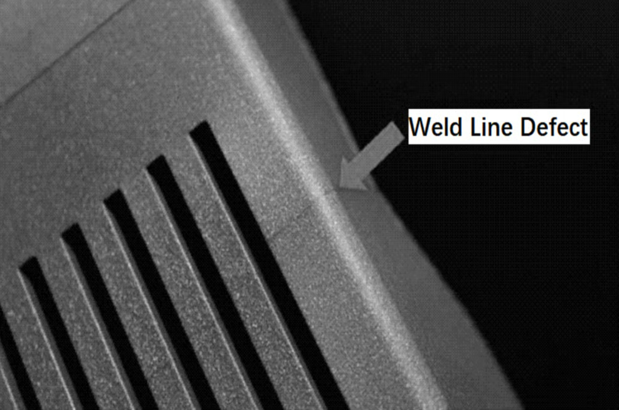
Weld Line Management:
Weld lines (knit lines) occur where two flow fronts meet. If they don’t fuse completely due to insufficient temperature or pressure, they create a weak plane.
Mitigation strategies:
- Mold Flow Analysis: Use software to predict weld line locations before cutting steel
- Relocate Gates: Position so weld lines occur in non-critical areas
- Second Shot Coverage: Design so critical weld lines are covered by overmold
- Process Optimization: Increase injection speed by 15-25% and mold temperature by 10°C to improve fusion
Real-World Engineering Applications
Automotive: Performance Under Extreme Conditions
Market share: 42.6% of global two shot molding applications
Typical Components You Can Design:
-
Interior Controls & Switches
- Substrate: PC/ABS (structural rigidity + impact resistance)
- Overmold: TPE Shore A 50-70 (soft-touch feel)
- Requirements: Backlit translucency + 100,000 cycle durability
- Key challenge: Maintaining adhesion after thermal cycling -40°C to +85°C
-
Sealed Electrical Connectors
- Substrate: PA66 GF30 (glass-filled for strength)
- Overmold: TPE-V or silicone (IP67 environmental sealing)
- Requirements: Chemical resistance to oils/coolants
- Design focus: Compression seal geometry around contact pins
-
Gear Shift Knobs
- Substrate: PC or PBT (high heat deflection temperature)
- Overmold: TPU Shore A 80-90 (abrasion resistance)
- Requirements: 500,000+ cycle life, vibration dampening
- Bond requirement: Minimum 12 N/mm peel strength
Engineering advantage: Integrated seals eliminate the assembly tolerance stack-up that causes 60-70% of field failures in traditional designs.
Medical Devices: Precision Meets Biocompatibility
Fastest growing segment: 9%+ CAGR through 2032
Critical Applications:
-
Surgical Instrument Handles
- Substrate: Medical-grade PEEK or PC
- Overmold: Medical TPE (USP Class VI certified)
- Requirements: Sterilization compatibility (autoclave, gamma, EtO)
- Design consideration: Eliminate bacteria-harboring gaps
-
Auto-Injector Pens
- Substrate: COC or COP (drug compatibility)
- Overmold: Medical-grade TPE for grip + integrated plunger seal
- Requirements: <10 N injection force, hermetic sealing
- Regulatory: ISO 13485 compliance for single-component assembly
-
CPAP Mask Interfaces
- Substrate: PC or PP (rigid frame)
- Overmold: Medical silicone (Shore A 20-30 for comfort)
- Requirements: Leak rate <20 L/min at 20 cmH₂O pressure
- Key specification: Skin contact duration >8 hours without irritation
Why two shot molding wins here: Eliminates adhesive bonding (potential contamination source) and creates seamless, cleanable surfaces that meet FDA guidelines.
Consumer Electronics & Power Tools
Design Requirements:
-
Smartphone Cases with Shock Absorption
- Substrate: PC (optical clarity + rigidity)
- Overmold: TPU Shore A 85-95 (corner protection)
- Drop test: 1.5m onto concrete, 26 impacts
- Dimensional stability: ±0.1mm for camera cutouts
-
Power Tool Handles
- Substrate: PA66 GF30 (structural strength)
- Overmold: TPE-V with vibration dampening compounds
- Requirements: Reduce handle vibration by 40% (ISO 5349)
- Durability: 50,000+ actuation cycles without delamination
Engineering insight: Strategic placement of softer TPE reduces user fatigue by 30-40% compared to hard plastic alone, as measured by ergonomic grip pressure studies.
Process Control and Troubleshooting
Critical Process Parameters
Monitor and control these for consistent quality:
First Shot Parameters:
| Parameter | Typical Range | Impact if Out of Spec |
|---|---|---|
| Melt Temperature | ±5°C target | ±10°C causes flow length variation >15% |
| Injection Pressure | 800-1600 bar | Low: short shots; High: flash |
| Cooling Time | 70-85% solidification | Insufficient: substrate deformation in shot 2 |
| Mold Temperature | ±3°C target | Affects surface energy for bonding |
Second Shot Parameters:
| Parameter | Typical Range | Impact if Out of Spec |
|---|---|---|
| Melt Temperature | 10-30°C below substrate melt | Too high: substrate melts; Too low: poor bonding |
| Pack Time | 2-5 seconds | Insufficient: weak molecular diffusion |
| Injection Speed | Medium to high | Affects weld line strength |
Common Defects and Solutions
Problem: Poor Bond Strength (Peel <8 N/mm)
Root causes:
-
Substrate cooled too much before shot 2
- Solution: Reduce first shot cooling time by 10-20%
- Verify substrate temperature >40°C above Tg at shot 2
-
Material incompatibility
- Solution: Switch to chemically compatible TPE grade
- Add mechanical interlocks (0.5-1.5mm undercuts)
-
Surface contamination
- Solution: Increase purge cycles; check for mold release residue
- Consider surface treatment or primers for difficult combinations
Problem: Flash at Material Interface
Root causes:
-
Insufficient shut-off compression
- Solution: Increase accent groove depth to 2.0-2.5mm
- Verify clamping force meets 3-5 tons per projected area
-
Substrate warpage
- Solution: Optimize first shot cooling uniformity
- Add ribs or thickness to stabilize substrate geometry
Problem: Weld Lines in Critical Areas
Root causes:
-
Poor gate location
- Solution: Relocate gates using mold flow analysis
- Add overflow wells to carry weld lines out of part
-
Insufficient injection pressure
- Solution: Increase pressure by 10-15%; increase melt temp by 10°C
Design Validation Checklist
Before releasing your design for tooling:
Material Selection:
- [ ] Confirmed chemical compatibility with peel testing (>10 N/mm target)
- [ ] Verified thermal processing windows overlap (30°C minimum differential)
- [ ] Validated environmental resistance (temperature, chemicals, UV)
- [ ] Confirmed regulatory compliance for application (medical, automotive, etc.)
Geometry:
- [ ] Wall thickness 40-60% of adjacent sections minimum
- [ ] Transitions <25% change per 3mm flow length
- [ ] Draft angles ≥3° on shut-off surfaces, 5° on textured areas
- [ ] Accent groove 1.5-2.0mm depth at material interface
Mechanical Features:
- [ ] Undercuts 0.5-1.5mm depth on PP substrates (mandatory)
- [ ] Surface texture SPI C-2 or coarser for mechanical bonding
- [ ] Through-holes for complete encapsulation where possible
Manufacturing:
- [ ] Gate locations avoid high-stress areas
- [ ] Weld lines predicted via mold flow analysis
- [ ] Runner shutoff mechanism designed for alternating shots
- [ ] Ejection system accounts for dual-material stiffness
Testing Plan:
- [ ] Peel strength testing per ASTM D1876 or ISO 11339
- [ ] Environmental cycling -40°C to +85°C, 500 cycles minimum
- [ ] Dimensional verification ±0.05-0.15mm critical features
- [ ] Functional testing per application requirements
Seamless Transition from Your Current Process
You Don’t Need to Change Your Entire Manufacturing Strategy
If you’re currently using traditional overmolding or adhesive assembly, Shanbo can help you transition to two shot molding with minimal disruption:
What We Handle:
- Tooling modification or redesign to accommodate rotary platen requirements
- Material compatibility validation and peel strength testing
- Process development and parameter optimization
- First article approval and dimensional verification
- Production ramp-up with SPC monitoring
What You Get:
- 40-60% reduction in cycle time vs. traditional overmolding
- Elimination of adhesive curing time (typically 24-72 hours)
- Improved dimensional consistency (±0.02mm vs. ±0.15mm)
- Stronger material bonds (12-18 N/mm vs. 6-10 N/mm for adhesives)
- Reduced total part count in your BOM
No Minimum Volume Requirements for Initial Validation
We understand you need to prove the concept before committing to high-volume tooling. Our approach:
- Soft tooling for 500-1000 parts validation runs
- Production intent materials and processes
- Full dimensional and functional testing
- Amortized tooling costs for production commitments >50,000 units
Get Started: Free DFM Review
Send us your current design and we’ll provide:
- Material compatibility assessment for your application
- Preliminary tooling cost estimate
- Cycle time projection and annual capacity calculation
- Identification of potential design optimizations
Within 48 hours, you’ll have a preliminary assessment of feasibility and a roadmap to prototype validation.
Frequently Asked Questions
Q: What’s the minimum production volume where two shot molding becomes cost-effective compared to assembly?
A: The break-even point typically occurs at 10,000-50,000 units annually depending on part complexity. However, for components requiring 3+ assembly operations, or where seal integrity is critical, the economics can favor two shot molding at volumes as low as 5,000 units due to eliminated secondary processes and reduced quality issues.
Q: Can you convert my existing overmolding design to two shot without major changes?
A: In most cases, yes, with minor modifications. The key areas requiring attention are: (1) shut-off zone design (adding accent grooves), (2) gate location optimization, and (3) mechanical interlock features if substrate material is PP or other non-polar polymers. We typically recommend a DFM review to identify specific changes needed for your design.
Q: How do I know if my material combination will bond properly?
A: Material compatibility depends on chemical structure similarity. PC, ABS, and PA generally bond well with polyurethane-based or styrenic TPEs. PP requires mechanical interlocking due to minimal chemical affinity. We recommend peel strength testing (ASTM D1876) with production-intent materials before committing to tooling. Target minimum 8-10 N/mm for structural applications, 12-15 N/mm for high-stress applications.
Q: What tolerances are realistic for two shot molded parts?
A: For critical dimensions on the substrate (first shot), expect ±0.05-0.10mm. The material interface position can be held to ±0.02mm with proper tooling design. Features created by the overmold (second shot) typically achieve ±0.10-0.15mm due to the compliance of elastomeric materials. These tolerances assume proper DFM principles and optimized process control.
Q: How long does tooling development typically take?
A: For production intent tooling:
- Soft tooling (aluminum): 4-6 weeks to first shots
- Production tooling (hardened steel): 8-12 weeks to first shots
- Process optimization: Additional 2-4 weeks for parameter validation
- PPAP/first article: 1-2 weeks for dimensional verification and approvals
Timeline can be accelerated with parallel engineering activities during tooling fabrication.
Q: What about environmental testing and durability?
A: Two shot molded parts typically undergo:
- Thermal cycling: -40°C to +85°C (automotive standard)
- Humidity exposure: 85% RH at 85°C per IPC standards
- Chemical resistance: Application-specific (oils, solvents, cleaning agents)
- UV stability: ASTM G154 for exterior applications
- Peel strength degradation: <15% strength loss after environmental exposure
We can coordinate third-party testing or provide in-house validation data for standard material combinations.