
Hardware startups often hit a wall called the “Valley of Death.”
You have a working prototype. You need 1,000 units to prove the market. But mass production factories want orders of 100,000, and 3D printing isn’t durable enough for the field.
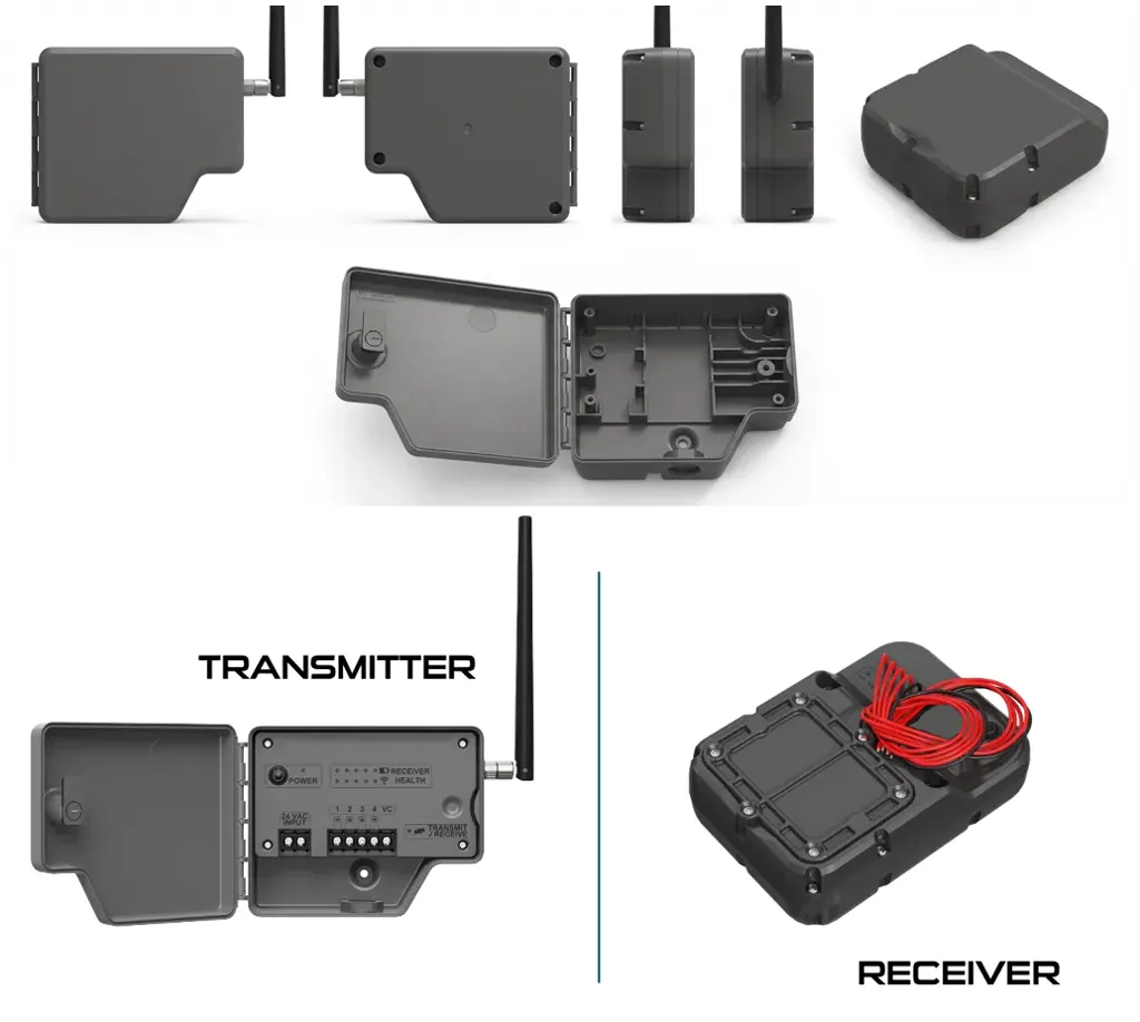
We recently worked with a North American company building wireless irrigation valve controllers. Their problem was specific: the device sits in mud, rain, and valve boxes. It needs to stay dry.

They needed 1,000 units initially. Then 10,000. And they needed a guaranteed IP67 rating.
This isn’t a sales pitch. This is a record of the engineering trade-offs, failures, and material science required to make that happen.
The Physics of Waterproofing
IP67 isn’t just a marketing sticker. It means the enclosure is dust-tight and can survive immersion in one meter of water for 30 minutes.
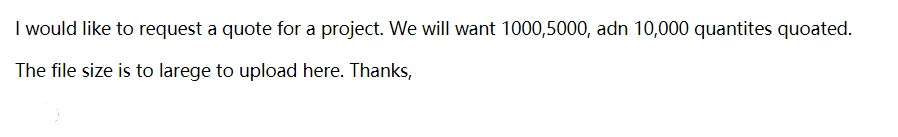
Many engineers try to solve this with screws and a rubber gasket. That works for a while. But gaskets degrade, and screws provide uneven pressure. For a permanent outdoor device, the plastic parts need to become one single piece. Molecular-level integration is required.
We utilized ultrasonic welding. It’s fast and clean, but the joint design is the most critical factor. You can’t just press two flat surfaces together and vibrate them.
Material Selection and Joint Design Trade-offs
We had to choose the right plastic. This decision dictated the mold design.
If we used Amorphous Polymers (like ABS, Polycarbonate, or Polystyrene):
These are easier to weld. We would use a “butt joint” with an energy director. This is a small triangular ridge molded into the surface. It focuses the vibration energy at a sharp point, melting the ridge and flowing it across the joint.
(Note: For Polycarbonate, the standard 90-degree angle on the energy director isn’t sharp enough. We use a 60-degree angle to concentrate the energy better.)
However, the client considered Crystalline Resins (like Nylon/PA66 or Polypropylene) for better chemical resistance against fertilizers.
Here is where standard energy directors fail. In crystalline materials, the molten plastic solidifies instantly once the vibration stops. It creates a “cold weld” that is weak and leaks.
For crystalline resins, we must use a Shear Joint.
| Feature | Energy Director (Amorphous) | Shear Joint (Crystalline) |
|---|---|---|
| Mechanism | Melts a ridge between flat surfaces | Telescoping fit (parts slide into each other) |
| Melting Action | Flows across the joint | Smears along vertical walls |
| Advantage | Simple tool design | Eliminates voids; prevents air contact |
| Risk | Weak bond in crystalline materials | Requires rigid sidewall support (fixture) |
We advised the shear joint approach if they went with Nylon. The smearing action prevents the molten plastic from touching air, which eliminates leak paths. But it requires a fixture to prevent “hoop stress” (the part bulging outward), or the seal fails.
Failure Record: The Moisture Trap
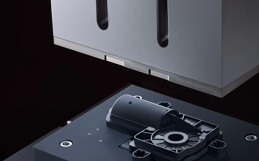
During the pilot run, we encountered a failure with the Nylon housings. The welding parameters were correct, but the joints leaked.
The cause was hygroscopicity. Materials like Nylon and Polycarbonate absorb moisture from the air.
When we welded parts that had been sitting out for a day, the trapped water inside the plastic boiled instantly. This created a foamy, porous structure at the weld interface. It looked welded, but under a microscope, it was a sponge.
Correction: We changed the process to weld parts immediately after they came out of the injection mold. If that wasn’t possible, they had to be stored with desiccants.
The Switch to Servo-Driven Welding
In the past, we used pneumatic welding systems. They apply constant force. The problem is that molded parts have slight size variations. If a part is 0.1mm taller, a pneumatic welder based on time might not melt it enough, or might melt it too much.
For this project, we used servo-driven systems. They allow “velocity profiling”.
This achieves “melt-match“. The horn (the vibrating tool) moves down at the exact speed the plastic is melting.
Crucially, we switched to welding by absolute distance.
- Old way: Weld for 0.5 seconds. (Inconsistent melt volume if part size varies).
- New way: Weld until the assembly collapses exactly 1.2mm. (Consistent final height).
This reduced residual stress in the part, which improved the burst pressure rating.
Calculating the Leak Test
Dunking 1,000 units in a water tank is slow, messy, and bad for the electronics if they fail.
We used Differential Pressure Decay testing using air.
Here is the logic (and the math):
- Pressure Target: IP67 at 1 meter depth equals approximately 100 mbar of pressure differential.
- Critical Hole Size: Research shows water generally won’t flow through a hole smaller than 20 micrometers due to surface tension.
- Air vs. Water: Air molecules are much smaller and less viscous than water.
If air cannot escape, water certainly cannot get in.
We set the reject limit at 0.01 sccm (standard cubic centimeters per minute).
(This is a conservative margin. The “screen door” analogy explains it best: Air blows through a screen, but water beads up on the mesh because of surface tension. We just need to ensure the “holes” in our weld are smaller than 20 microns.)
Conformal Coating Protection
The housing is the primary shield. But condensation happens inside valve boxes. The PCBA needed its own armor.
We looked at the options:
- Acrylic: Easy to rework (dissolves in solvent). Verdict: Rejected. Poor chemical resistance.
- Epoxy: Rock hard. Verdict: Rejected. Too rigid. It might crack components during thermal cycling (hot days, cold nights).
- Silicone: Flexible and heat resistant. Verdict: Selected. It works well for automotive-style outdoor applications.
Process Note: We had to clean flux residues thoroughly before coating. We also discussed Plasma Treatment to increase surface energy and adhesion, but for this volume, thorough cleaning was sufficient.
From 1,000 to 10,000
The first 1,000 units were a learning curve regarding moisture control and weld collapse distance.
But because we validated the process with data (pressure decay curves, weld collapse depth), scaling to 10,000 units was a matter of replication, not reinvention.
Startups often ask for “mass production quality” on prototype volumes. It’s possible, but it requires using production-grade materials and processes (like servo welding and DFM) from day one, rather than relying on silicone glues and temporary fixes.
FAQ
Q: Why use air to test for water leaks?
A: It’s faster and non-destructive. Air molecules are smaller than water. If the enclosure holds air pressure (leak rate < 0.01 sccm), water, which has high surface tension, physically cannot enter.
Q: Can I use screws and a gasket for IP67?
A: You can, but it’s risky for long-term outdoor use. Screws can loosen with thermal cycling, and gaskets can degrade. Ultrasonic welding creates a hermetic seal by fusing the plastic at a molecular level.
Q: Why did my Nylon parts leak after welding?
A: Probably moisture. Nylon absorbs water from the air (hygroscopic). If you weld moist Nylon, the water boils and creates foam in the joint. Dry your parts or weld them immediately after molding.
Q: What is the difference between an Energy Director and a Shear Joint?
A: An Energy Director (triangular ridge) is for amorphous plastics like ABS. A Shear Joint (telescoping interference fit) is for crystalline plastics like Nylon to prevent “cold welds”.
Q: Is low volume injection molding expensive?
A: The per-unit cost is higher than a million-unit run, but it’s often cheaper than machining or 3D printing 1,000 units. The key is using a “soft mold” or a Master Unit Die (MUD) system to lower tooling costs while still getting real injection-molded parts.
Q: Do I really need conformal coating if the box is sealed?
A: Yes. Air inside the box contains moisture. When the temperature drops, that moisture condenses. Conformal coating prevents dendritic growth and short circuits on the PCB.